
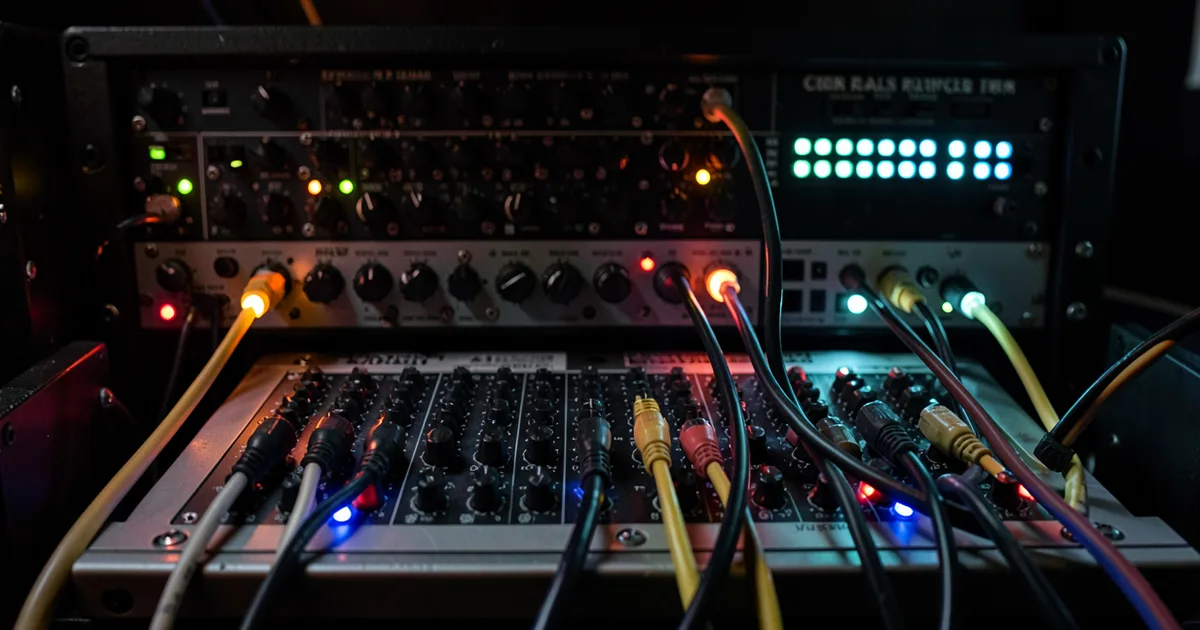
A patchbay is a panel of sockets that centralises every input and output in your studio into one place, so you can re-route any piece of gear to any other without crawling behind racks or unplugging cables from the back of your interface. Set one up correctly and you'll cut session routing time from minutes to seconds.
If you've ever spent four minutes hunting behind your desk for the insert return on your compressor while a vocalist waits, you already understand the value of a patchbay. It's not nostalgia hardware. It's not a relic from the tape era kept alive by tradition. It's a workflow tool, and a well-wired one saves real, measurable time every single session.
We've wired up studios from project rooms to mid-sized commercial rooms, and the question we hear most often is: "Do I actually need one?" Our answer is usually the same. If you own more than two pieces of outboard gear and you're still plugging directly into the back of your interface, you do.
This guide covers everything. Types, normalling configurations, connectors, wiring strategy, cost, troubleshooting, and how a patchbay fits into a hybrid analog/digital rig in 2024.
What Are the Different Types of Patchbay?
There are four physical formats and four normalling configurations. Those are separate things. Confusing them is the source of half the bad patchbay advice online.
Physical Formats
TRS 1/4" (bantam alternative): The most common format for project studios. Each socket accepts a standard balanced TRS or unbalanced TS jack. A single 1U rack unit typically holds 48 sockets, arranged as two rows of 24. The Neutrik NYS-SPP-L sits here, at around $100 for a 48-point unit. Affordable, widely compatible, and the right starting point for most setups.
TT (Tiny Telephone / Bantam): Smaller jacks, denser panel. A 1U unit can fit 96 TT points instead of 48 TRS points. The Switchcraft StudioPatch 9625 gives you 96 points (48 channels) with DB-25 inputs and outputs. This is professional-grade infrastructure. The connectors are more fragile if you're patching aggressively, but the density is unbeatable in large rooms with lots of gear.
XLR patchbays: Less common, but they exist for mic-level routing. Useful if you're managing multiple mic preamps or re-routing microphones between rooms. Larger footprint per point, so they eat rack space fast.
Hybrid and DB-25 systems: Some patchbays use DB-25 (also called D-sub) connectors on the rear for multi-channel snaking to interfaces and outboard. The Redco TT/DB25 range is the reference point here. Cleaner rear-panel wiring, but it requires compatible gear or custom looms. Adds cost, pays back in tidiness.
Normalling Configurations
This is where most guides go vague. We won't.
Full-normal: Top and bottom rows are connected internally until you insert a cable. Patch into the top jack, the connection breaks. Patch into the bottom jack, the connection also breaks. Works best for gear you always want connected by default but need to interrupt occasionally, like an insert across a channel strip.
Half-normal: Top and bottom rows are connected internally, but patching into the bottom jack does NOT break the connection. The signal splits instead. Top row still sends to the bottom row, but patching the bottom also taps that signal elsewhere. Brilliant for monitoring splits or parallel processing without breaking your main signal path.
Through (non-normal): No internal connection. Top and bottom rows are completely independent. You patch everything manually every time. Frustrating for permanent connections, but right for flexible routing where you never want a default state.
Switchable normal: The best of all worlds, and worth the price premium. The Samson S-Patch Plus is a 48-point unit with per-channel switch on the front panel for normal, half-normal, and through. We love this feature on hybrid rigs where the same patchbay handles both permanent and session-by-session routing.
How Do You Wire a Patchbay Correctly?
The wiring strategy matters more than the patchbay itself. A $100 unit wired correctly will outperform a $400 unit wired badly every time.
The Standard Layout Logic
Every patchbay point is two jacks: top row and bottom row. The convention is outputs on top, inputs on bottom. This mimics signal flow: signal comes out of something (top), goes into something else (bottom). Break that convention and your brain will fight the panel for years.
We wire studios with this column structure: interface outputs on the top row, interface inputs on the bottom row of the same columns. Outboard gear outputs go on top rows of adjacent columns, their inputs on the bottom. Set those columns to half-normal and your interface feeds the outboard by default. Patch a cable to interrupt or redirect as needed.
Labelling
Label every single point before you patch your first cable. Not after. A P-Touch label maker and an afternoon of honest documentation will save you hours of mystery debugging six months from now. We use a consistent format: [DEVICE ABBREVIATION] [IN/OUT] [CHANNEL NUMBER]. So: "RV IN 1" for reverb unit input channel 1.
Cabling Budget
Plan to spend 10-20% of your total gear investment on cabling alone. A studio with $3,000 in outboard should budget $300-$600 for quality cable, connectors, and the patchbay itself. Cut this corner and you'll be chasing noise and ground loops instead of making music.
Pre-wired TRS patchbays save setup time. DIY wiring with Neutrik connectors and Mogami 2534 cable costs more time but less money, and gives you exact cable lengths. For a 48-point bay, we estimate 6-10 hours of soldering for a first build. That time pays back quickly.
What Connectors Do You Actually Need?
Three connector types cover almost every studio scenario.
TRS 1/4" (balanced): Two conductors plus ground. Carries a balanced signal, which rejects noise over long cable runs. Use these for line-level connections between outboard units, interfaces, and patchbays wherever possible. The noise rejection is worth the marginal extra cost over TS.
TS 1/4" (unbalanced): One conductor plus ground. Fine for short runs under about 3 meters, or for instruments running into DI boxes. Many vintage synths output TS. You can plug TS into a TRS patchbay without issue, but you'll lose the noise rejection.
XLR: Three-pin, balanced, and the standard for microphone-level signals. If you're patching microphones or mic preamp outputs, XLR is the correct choice. Using TRS adaptors at mic level works, but it's inelegant and adds one more potential failure point.
The one connector type most guides forget: the DB-25 multipin. One DB-25 connector carries 8 balanced channels. If you're wiring a studio with 16 or more channels of I/O, a DB-25 loom to the rear of your patchbay is the tidy professional approach. It's what the Redco and Switchcraft pro units are designed around.
How Do Phantom Power and Microphones Interact With Patchbays?
This is the most dangerous mistake in patchbay wiring. We've seen it kill preamps.
Phantom power (48V DC) is sent down XLR cables to power condenser microphones. It's harmless to balanced dynamic mics and ribbon mics with balanced outputs. It can destroy unbalanced ribbon mics and some older dynamic mics if a wiring fault sends phantom down an uneven path.
The rule: never route phantom power through a standard TRS patchbay. The jacks are not rated for 48V, and during connect/disconnect the voltage can spike across the wrong conductors. If you're patching microphone signals, use a dedicated XLR patchbay, or a preamp-to-patchbay connection only after the preamp has amplified to line level (where phantom is no longer present).
We once ran a condenser mic feed through a TRS bay on a rush session. The preamp held up, but we spent 20 minutes chasing a buzz that turned out to be a partially-seated TRS jack creating a momentary ground fault. Annoying, and avoidable.
Where Does a Patchbay Fit in a Hybrid Analog/Digital Studio?
This is the question most guides avoid. It's also where a patchbay earns its place most clearly in 2024.
A modern hybrid studio runs a DAW as the core, with a hardware interface for I/O, and outboard gear for processing. The interface has a finite number of physical inputs and outputs. Without a patchbay, every re-routing means unplugging something at the back of the interface or the back of the outboard unit.
With a patchbay, your interface outputs are always wired to the patchbay. Your outboard gear inputs and outputs are always wired to the patchbay. Routing from the DAW through a hardware compressor and back is a single patch cable inserted in two seconds.
Hybrid Routing in Practice
Here's how we wired a 16-channel hybrid room. Interface outputs 1-16 occupied the top row of the first two columns. Interface inputs 1-16 occupied the bottom row of those same columns. Outboard gear: two compressors, one EQ, and one reverb unit filled the next four columns, half-normal so the interface fed each unit by default. The last two columns were left as "through" for flexible patching with external synths and processors.
Total reconfiguration time for a new session routing: under 30 seconds. Without the patchbay, the same change was a four-minute adventure behind the rack. That's 30+ minutes saved on a busy six-song day.
MIDI Patchbays
Most audio patchbay guides skip this. Dedicated MIDI patchbays, like the MIDI Solutions Quadra Thru or the iConnectivity mioXL, apply the same logic to MIDI routing. If you have more than three hardware MIDI devices, a MIDI patchbay removes the daisy-chain dependency and gives each device its own direct path. Software MIDI routing inside the DAW handles most cases, but hardware MIDI patching removes latency from the routing layer entirely.
How Do You Troubleshoot Ground Loops and Impedance Problems?
Ground loops are the most common patchbay problem. They show up as a 50Hz or 60Hz hum that appears when you connect two pieces of gear. The cause is almost always two devices connected to different ground potentials, creating a loop that acts as an antenna for electrical interference.
The fix is not a ground lift adapter as a permanent solution. That's dangerous on mains-powered gear.
The real fix: route all studio gear through the same power distribution unit (PDU) on the same circuit. This equalises ground potential across everything. Jensen Transformers make isolation transformers (the JT-11P-1 is a standard reference) that break the ground loop at the signal level without compromising safety. They're expensive, around $100 per channel, but they're the correct long-term solution for persistent ground loop problems.
Impedance mismatch is a different problem. It shows up as signal loss or high-frequency rolloff when connecting gear with mismatched input/output impedances. The standard rule: output impedance should be at least 10x lower than input impedance. Most modern studio gear follows this, but vintage outboard units sometimes don't. A DI box or impedance-matching transformer solves this at the connection point.
Quick Diagnostic Process
Hear hum? Remove the patchbay from the chain completely and connect the same two pieces of gear directly. Hum persists: ground loop is in the power, not the patchbay. Hum disappears: the patchbay cabling has a wiring fault, likely a shield connected on both ends where it should only be connected on one.
Worth Bookmarking
- Redco Audio, Custom patchbay wiring looms, TT/DB-25 panels, and cable assembly at professional grade. One of the most useful ordering resources for studio infrastructure.
- Jensen Transformers, The reference site for understanding and solving impedance and ground loop problems. Their application notes are free and excellent.
- Rane Note 110 (Star Quad Cable), A free technical note on balanced audio, cable types, and why shielding strategy matters. Dry reading, genuinely useful knowledge.
- Gearslutz / Gearspace, The studio wiring forum threads here are some of the most practical patchbay troubleshooting resources available. Search "patchbay wiring" for years of real-world experience.
- iConnectivity, For MIDI patchbay solutions in hybrid studios. The mioXL is the current reference unit for complex hardware MIDI routing.
Summary
A patchbay centralises every connection in your studio and cuts routing time from minutes to seconds. TRS 1/4" units suit most project studios. TT/bantam suits larger professional setups. Half-normal is the workhorse configuration. Full-normal handles inserts. Switchable units give you flexibility. Wire outputs on top, inputs on bottom, label everything before you start, and never route phantom power through a standard TRS bay. Budget 10-20% of your gear spend on cabling. Solve ground loops at the power level, not with cheap adapters. Set it up once, correctly, and it runs silently in the background of every session you'll ever do.
Part of our complete Studio Signal Chain Guide: Build a Clean Audio Path series.
Frequently Asked Questions
Do I need a patchbay if I only use plugins in my DAW?
Probably not. A patchbay solves hardware routing problems. If your signal chain lives entirely inside the box with no physical outboard gear, a patchbay adds complexity without benefit. The moment you add a hardware compressor, EQ, or external synth to a permanent position in your rig, the case for one gets strong fast.
What's the difference between half-normal and full-normal, practically?
Half-normal keeps the internal connection active when you plug into the bottom jack, so your signal splits to two destinations. Full-normal breaks the connection when you plug into either jack. Use full-normal for inserts you need to interrupt. Use half-normal for monitoring, parallel processing, or anywhere you want to tap a signal without killing the original path.
How many rack spaces does a patchbay take up?
A standard TRS 1U patchbay holds 48 points (24 channels) in a single rack unit. A TT bantam 1U panel holds 96 points (48 channels). If you need 32 channels of patching in TRS format, plan for at least 2U. Budget rack space accordingly, and leave 1U of free space above each patchbay for easy cable access.
Can I mix TRS and TS cables in the same patchbay?
Yes. A TRS socket accepts both TRS and TS plugs. Inserting a TS plug into a TRS jack shorts the ring conductor to ground, which converts a balanced connection to unbalanced. For short cable runs under 3 meters this is fine. For longer runs or noisy environments, you'll want balanced TRS throughout.
How much should I expect to spend on a patchbay setup?
A basic 48-point TRS patchbay runs around $80-$150 for a quality unit like the Neutrik NYS-SPP-L. Add $150-$300 for quality cable and connectors for a full studio wiring job. Pre-wired solutions cost more upfront but save 6-10 hours of soldering. Total realistic budget for a project studio patchbay setup: $250-$500. That's a one-time cost that pays back in session time within a month of regular use.
What's the easiest way to avoid ground loops when wiring a patchbay?
Power all your studio gear from the same circuit on the same PDU. This is step one and it solves most ground loop problems before they start. If you still hear 50/60Hz hum after that, use an isolation transformer like the Jensen JT-11P-1 at the connection point creating the loop. Never use a permanent ground-lift on mains-powered gear.