What You'll Need
- 48-point TRS patchbay (we recommend the Neutrik NYS-SPP-L1 at under $99)
- TRS patch cables (budget 10-15% of your total gear cost on cabling)
- Rack space: 1U per 48-point bay
- Screwdriver, rack screws, cable ties
- A wiring diagram (paper or digital, we'll build one)
- Skill level: Beginner-friendly. If you can plug in a guitar, you can do this.
- Estimated time: 2-4 hours for a typical 8-12 piece studio rig
A patchbay is a central hub that connects every piece of gear in your studio so you can reroute signal paths from the front without crawling behind your rack every session. That’s the whole thing. The fear around patchbays is overblown. Once you understand which direction signal flows and how normalling works, the setup is mostly cable management with a labeling session at the end. We’ve done this in project rooms with four pieces of gear and rooms with forty. The process is identical.
Step 1, Draw Your Signal Flow Before Touching Anything
Don’t touch a cable yet. Grab paper or open a drawing app and map every piece of gear you own.
List each device and note: does it send signal, receive signal, or both? Your audio interface sends and receives. Your compressor receives on the input and sends on the output. Your reverb unit does the same. Your monitors only receive.
Now draw arrows. Source to destination. Every connection you currently make manually is a connection that will live on your patchbay. This diagram becomes your wiring map for the rear panel and your reference when labeling the front. Keep it. Update it when gear changes.
We’d estimate 80% of patchbay confusion comes from skipping this step. Don’t skip it.
Step 2, Choose the Right Patchbay Format
For most home and project studios, a 48-point TRS bay is the right call. Full stop.
The Neutrik NYS-SPP-L1 gives you 48 TRS jacks (24 pairs) in 1U for under $99. It handles balanced and unbalanced connections and accepts standard ¼-inch TRS patch cables you’ll find everywhere.
TT (Tiny Telephone or Bantam) bays fit 96 points in 1U. They’re used in professional broadcast and high-density commercial rooms. TT cables are harder to find, more expensive, and the connectors are fiddlier to work with. If you don’t have more than 24 physical devices, TT is overkill. We’d skip it entirely until you’re running a facility-level operation.
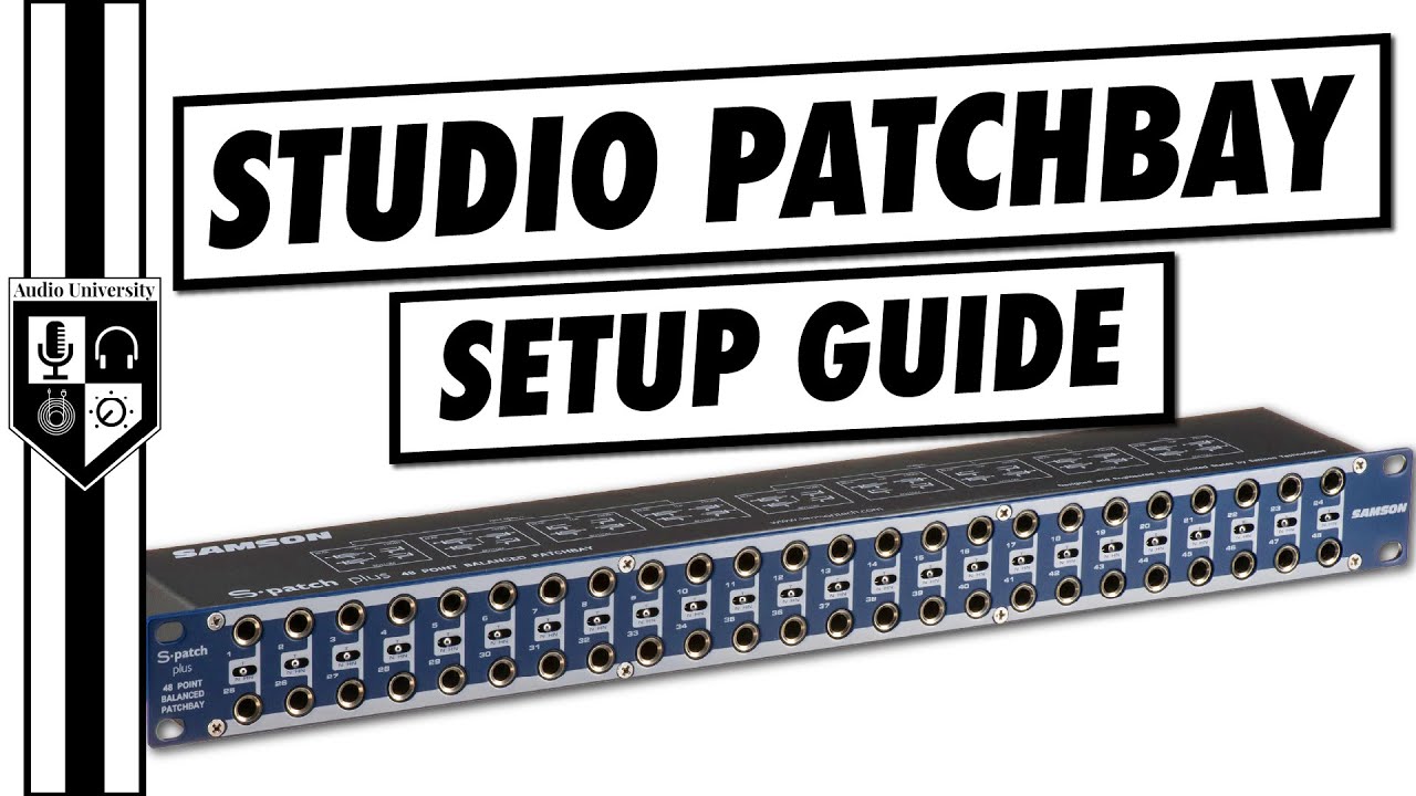
The Samson S-Patch Plus sits in a similar price bracket to the Neutrik but trends more expensive for comparable point counts. Check manufacturer sites for current pricing on both before you buy.
Step 3, Understand the Two-Row Layout
Every patchbay follows the same logic. Top row: sources. Bottom row: destinations.
Signal leaves a piece of gear, arrives at the top row. You want to send that signal somewhere, it leaves from the bottom row and travels to its destination. When you look at the front of your bay, you read it like a grid: top is “coming from”, bottom is “going to”.
On the rear panel, this flips. The rear top row jacks connect to the outputs of your gear. The rear bottom row jacks connect to the inputs. Keeping this consistent across all your bays stops the whole system from becoming a mystery.
Step 4, Learn the Three Normalling Modes
Normalling is how a patchbay routes signal when nothing is plugged into the front. Get this wrong and you’ll spend a frustrated afternoon wondering why your compressor isn’t doing anything.
Full-normal means the top row feeds directly into the bottom row beneath it with no front patch cable needed. Inserting a cable into either jack breaks the connection. Use this for gear that always runs in series, like a channel strip that always feeds a specific bus.
Half-normal keeps the internal connection active when you plug into the top jack, but breaks it when you plug into the bottom. This is your most useful mode. It lets you tap into a signal for monitoring or parallel processing without interrupting the default path.
Non-normal means top and bottom rows are completely independent. No internal connection exists. Use this for inputs and outputs that need total flexibility, like your interface’s aux sends.
Most 48-point bays let you set normalling per pair using internal switches or physical jumpers. We always half-normal our interface outputs by default.
Step 5, Wire the Rear Panel to Your Gear
This is the physical work. Set your patchbay in your rack first, then run cables from the rear panel to your equipment.
Rear top row, pair 1: plug one end into the output of your first source device (say, the output of your audio interface’s line out). The other end goes to the rear top jack. Rear bottom row, pair 1: plug one end into the rear bottom jack. The other end goes to the input of whatever device receives that signal (say, a hardware compressor input).
Work pair by pair. Don’t rush. Label each cable at both ends with tape as you go. A cable labeled “IF OUT 1” on one end and “COMP IN” on the other will save you hours later.
We connected our first patchbay in a noisy session, skipped labeling, and spent the next month yanking wrong cables. Annoying doesn’t cover it.
Step 6, Set Normalling Per Section
Once all rear cables are in place, open the unit and set normalling for each pair before you close it up.
We typically do this: half-normal everything connected to our interface outputs and outboard gear insert points. Non-normal our monitor outs, headphone sends, and anything that should never accidentally feed somewhere. Full-normal only when we have a fixed, permanent chain that never changes.
Check your specific bay’s manual for how to switch normalling. The Neutrik NYS-SPP-L1 uses internal jumpers. Some bays have a rear-panel switch per pair. Set them thoughtfully. Changing normalling later means opening the unit again.
Step 7, Label the Front Panel Clearly
Your labeling system is the whole point. A patchbay with no labels is just chaos in a rack.
Use dymo tape or insert printed labels into the bay’s label strips if it has them. Label every single jack. Top row: the source (“IF OUT 1”, “COMP OUT”, “FX SEND”). Bottom row: the destination (“COMP IN”, “IF IN 1”, “FX RTN”). Be specific. “COMP” is useless when you own three compressors.
Color coding helps. We use red tape for interface I/O, blue for outboard, and yellow for monitor paths. Takes an extra twenty minutes to set up. Saves the same amount every single session.
Step 8, Address Ground Loops Before They Start
Mixing balanced and unbalanced gear through the same patchbay causes ground loops. You’ll know one when you hear it: a low 50Hz or 60Hz hum that disappears when you unplug something.
Prevention beats cure. Where possible, use TRS cables for balanced gear and keep them separate from unbalanced TS-connected gear. If you must mix them through the same bay, run the unbalanced connections into a DI box or re-amping device first to convert the signal. Some engineers use isolated patchbays for problem rigs, but these cost considerably more.
If a hum appears after wiring, try lifting the ground on one device at a time using a ground-lift switch. Never use a ground-lift adapter on a mains connection as a permanent fix. That’s a fire risk.
Step 9, Test Every Path With Signal
Before you call the job done, run signal through every single pair.
Play audio through your DAW and patch each pair at the front in turn. You’re checking that sound arrives where your wiring diagram says it should. No surprises allowed at this stage.
We once wired a session room where pairs 7 and 8 were accidentally swapped at the rear. Both worked. Neither worked correctly. It only showed up when we tried to insert a compressor on the wrong channel. The test session found it in two minutes. A live session would have found it in the worst possible way.
Step 10, Document the Final State
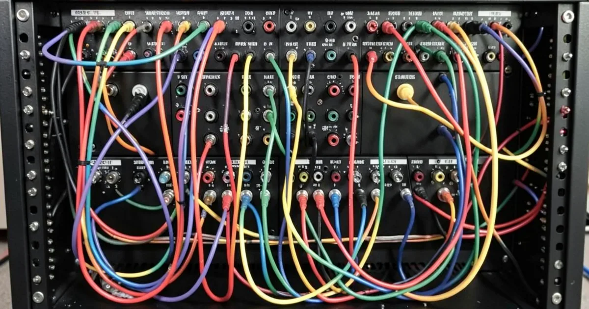
Update your wiring diagram to reflect the finished bay. Photograph the rear panel with cables in place. Note the normalling mode for each pair.
Store this somewhere you’ll actually find it. A folder in your DAW project template, a note in your phone, a laminated sheet in the rack drawer. When you add a piece of gear six months from now, you’ll know exactly where to wire it in without guessing.
A patchbay is only as useful as your documentation. A fully wired, unlabeled, undocumented bay is one power outage away from a very frustrating afternoon.
Pro Tips
Reserve two or three non-normalled pairs for utility. We call ours “scratch pads.” They’re blank pairs with no fixed assignment. Need to quickly insert a piece of gear for one session? Patch it there. This saves you from rewiring anything in your permanent setup.
Buy slightly more cable than you think you need. The math always lies. What looks like a 1-meter run from your rack to your outboard is usually 1.5 meters once you account for slack, strain relief, and routing. Budget for 20% more cable than your diagram suggests.
For hybrid ITB/outboard rigs with minimal I/O: Only patchbay what you actually use. If your interface has 8 line outputs and you only use 4 for outboard, patchbay only those 4. A half-populated bay is fine. Adding blank labels to empty pairs keeps the layout readable.
TT bays are for density, not quality. We get asked whether TT sounds better than TRS. It doesn’t. The connector format doesn’t affect audio quality at line level. If someone’s telling you otherwise, they’re trying to sell you expensive cables.
Common Mistakes to Avoid
Wiring rear inputs and outputs backwards. The most common error we see. A device’s output goes to the rear top row. Its input goes to the rear bottom row. Get this flipped and normalling does nothing useful, and you’ll spend an hour chasing a signal that’s going nowhere.
Full-normalling everything by default. Satisfying on paper. Annoying in practice. Full-normal means one cable on the front breaks your default signal path. Half-normal is almost always the better choice for gear you use regularly.
Ignoring the patchbay entirely for a “modern ITB setup.” We hear this one a lot. Even a two-rack-piece studio benefits from a patchbay if you swap gear configurations between sessions. The break-even point is faster than most people think: if you rearrange cables manually more than twice a week, a patchbay pays for itself in time within a month.
Cheap cables on expensive gear. The patchbay is only as good as the cables touching it. We’ve watched a brilliant $2,000 compressor sound inexplicably dull through no-brand patch cables with corroded connectors. Mogami or Hosa cables at minimum. Don’t underinvest here.
Frequently Asked Questions
Do I need a patchbay if I only have one or two pieces of outboard gear?
Probably not yet. A patchbay makes most sense when you're regularly changing what's connected to what. If your compressor lives permanently in an insert on your interface and never moves, just wire it directly and skip the bay for now. Add one when manual cable-swapping starts costing you session time.
What's the difference between a TRS patchbay and a balanced patchbay?
TRS jacks physically accept a tip-ring-sleeve connector, which can carry balanced or unbalanced signals depending on how your gear is wired. A "balanced patchbay" just means the chassis and routing are designed to preserve balanced signals correctly. Most quality 48-point bays, including the Neutrik NYS-SPP-L1, handle balanced TRS correctly. Check the spec sheet before buying anything budget-tier.
How many patchbays do most home studios need?
One 48-point bay handles most home studios comfortably. That's 24 pairs, covering your interface I/O, two or three pieces of outboard, and a few utility connections with room to spare. If you grow past 20 devices regularly in-use, a second bay makes sense. We'd say the average hybrid producer never needs more than two.